
Okay, that's a bit much all at once, and not complete either. Let's break it up a little bit. The first thing is that everything needs to have a name that the system can understand. First, let's take another look at the staging yard.

You might want to blow this up in another tab so you can switch back and forth while you follow along. The names in this case are numbers, which refer to various things. In this case, these are accessory numbers in the DCC system, so you don't have to worry about conflicts with locomotive numbers. Note that the card numbers, used for programming them in JMRI, can conflict with locomotive numbers. I get around this by using five digit card numbers. Also, as mentioned before, these are connected to a Digitrax Loco-Net network, and I'm using NCE to drive the trains, so the control systems are completely separate. These cards are from RR-Cirkits. For information on how to set up and connect these cards, go to their web site and download the manuals for the different cards. You will also need JMRI on a computer connected to the LocoNet to program the cards, but not to run the system.
I've got 12 staging tracks, and one main track coming in at the left, so there are 11 turnouts. Here is the numbering system for the turnouts:
| Turnout Names | ||
|---|---|---|
| Turnout |
Switch Motor
|
Track Circuit
|
| 601 | 601 | 621 |
| 602 | 602 | 622 |
| ... | ... | ... |
| 610 | 610 | 630 |
| 611 | 611 | 631 |
I left some out, but you get the idea. As mentioned in my last post, I'm using feedback from the switch machines to confirm the position, with one line for each track in the staging yard. Here are those numbers.
| Turnout Feedback | |
|---|---|
| Ladder lined for |
Input No.
|
| Track 1 | 651 |
| Track 2 | 652 |
| ... | ... |
| Track 11 | 661 |
| Track 12 | 662 |
Finally, there's this little panel to control the staging yard.

Here's the back of the panel.

This panel was made from a 4 x 6 picture frame. I replaced the glass with a piece of acrylic. It has a TowerMan card from RR-CirKits, a 12 position rotary switch, a SPST push button, and two LEDs. The graphics were printed on my color printer, cut to size, and had holes cut in it for the components. I removed the stand on the back board of the frame, and put a piece of that on the left side, wedged under the frame, to support the back when pushing the button. Not shown, but connected to the green terminal block on the right end of the card, is the Simple Serial Buss (SSB) connection. The nice thing about this is that the SSB doesn't have to be connected directly to the other cards it is controlling. It can be connected to any SSB port on the network. This greatly simplifies things.
The switch common wire (black) is connected to the ground connection on the TowerMan. The SPST switch (white) and the rotary contacts (blue) are connected to the I/O pins. The LEDs are connected with common anode to the "+" connection. The cathode wires are connected to I/O pins. Now it's time for another table.
| Panel I/O | ||
|---|---|---|
| I/O |
Description
|
No.
|
| Input | Rotary Pos. 1 | 1101 |
| Rotary Pos. 2 | 1102 | |
| ... | ... | |
| Rotary Pos. 12 | 1112 | |
| Push Button | 1113 | |
| Output | Red LED | 1114 |
| Green LED | 1115 | |
This panel should light up the green LED when the rotary switch is turned to the same track that is lined through the yard ladder. To line another track, turn the rotary switch, which turns off the green LED, to the track you want. Press the button, and the red LED starts flashing. When the ladder is lined to that track, the red LED turns off, and the green LED turns back on.
The inputs, on the I/O-1 A through I/O-2 B tabs in JMRI, are set up like this:

This is for input 1101, position 1 on the rotary switch. It is an Input, action is Normal, debounce is Default, and type is Block Detector. The type means that the input is ON when it is connected to ground. Primary event # is 1101, and in the table, polarity is Send Inverted, Sensor Message, on Both Transitions, which means it sends a signal both when the switch is closed and when it is opened. There are no second or third events. This ties the input #1 on the card to a specific action.
The outputs are set up like this:

You get some different options for outputs. The key here is the type for the red LED (1114) is Short Inv Blink, timing is 0.65 Sec, and polarity is respond inv. With the LEDs set up as common anode, and tied to the "+" terminal, this means that the LED will blink when it is turned on, and be dark when it is turned off. The green LED (1115) is set to Short Pulse, Steady, and respond inv. This means that will turn on and stay on until it is switched off. It's a short pulse that lasts forever!
Now we're ready for our first bit of programming. This is under the Logic A through Logic D tabs in JMRI. Here are the first two entries to make the green LED turn on.

I'll go through this one piece at a time.
- V1 (variable 1)
- LocoNet - this uses DCC accessory messages.
- Type "Sensor Message" - a switch input
- Addr 1101 - the input number for position 1 on the rotary switch
- C/T "C" - the switch is closed. This results from how the input was set up.
- "Eval" - the logic block evaluates this condition. The other option is "True", which means it is accepted as true regardless of the input value.
- "AND" - both V1 and V2 must be true
- The V2 pieces are the same, except the address is 651, which is the input for the ladder being lined to track 1.
- When "V1 and V2 ==> true", both have to be true.
- Delay "0.01 sec" - do it right now
- Multi 00 - just do it once
- Action - this section describes what happens when V1 and V2 are true
- LocoNet - sends DCC accessory message
- Send "Switch Request" - JMRI considers all of these to be requests to throw turnouts, even when we're doing other things.
- Addr 1115 - the output for the green LED
- C/T "C" - close, which turns on the LED
- Enable checked - if this isn't checked, it doesn't do anything
- End Logic Block not checked - the end of this block. See below.
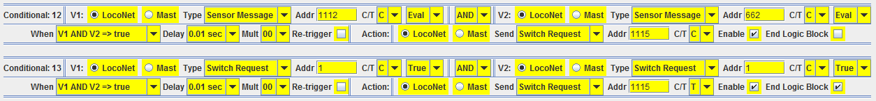
Conditional 12 is just like what we've just looked at, but with rotary switch input 1112 and turnout feedback input 662. Conditional 13 is different. V1 and V2 are set to "True" rather than "Eval". It will only get this far if all of the statements above it are FALSE. This is important to understanding how this programming works. Remember that the evaluation of a logic block STOPS as soon as it finds a statement that is TRUE. If it gets to Conditional 13, that means that none of the previous ones were true. In other words, the position of the rotary switch does not match the turnout position feedback. In this case, the green LED, output 1115 C/T is "T", or Thrown. This turns off the LED.
In practical terms, if the yard ladder is set for track 5 and the rotary switch is on 5, the green LED should be on. If you turn the rotary switch to, say, 4, that starts the evaluation of this logic block. It gets to Conditional 13 and turns the green LED off. Conversely, if something throws one of the switches so that the yard ladder is lined for track 8 instead of track 5, that also uses Conditional 13 to turn off the green LED. None of what we've done so far actually throws any of the switches in the yard ladder.
The logic block to turn the red flashing LED on and off is only two statements.

This logic block looks at the input for the push button, 1113, and output (Switch Request) for the green LED, 1115. Each statement has only one input, so the V2 section of both are set to True. When you press the button, input 1113, it triggers this logic block. Since it is pushed, 1113 is closed, so the output for the red LED is set to "T". Because of the way that flashing LEDs (remember "Inv Blink"?) are handled, this turn on the flashing red LED.
When you let go of the push button, 1113 is now set to "T", so Conditional 14 is FALSE, and it goes to Conditional 15. If the green LED, 1115, is off, i.e. "T", Conditional 15 is also FALSE, but that is the end of the logic block, so it does nothing. Doing nothing is an important choice in many cases. The red LED, which started blinking when you pressed the button, continues blinking, because nothing has told it to stop blinking.
If you turn the rotary switch or throw switches in the yard ladder so that the green LED, 1115, turns on ("C"), that also triggers this logic block. Assuming you aren't holding down the push button, it goes through Conditional 14, which is FALSE, and goes to Conditional 15, which is now TRUE, since 1115 is "C". That makes the red LED, 1114, "C", which in this case is OFF.
Note that if the green LED is on when you push the button, the red LED will start flashing, but will go back off when you let it go.
All of the logic we've looked at so far is in the TowerMan card on the panel. It doesn't have to be, it could be anywhere on any of the cards connected to the system, but it's easier to keep track of if it's close by. Also note that a logic block can extend from one tab (say, Logic A) to the next (Logic B) on ONE card, but cannot extend from one card to another. You can add a card to the system without using any of the inputs and outputs, just for a large logic block. In that case, the TowerMan is the least expensive. If your logic block won't fit on one card, you need to do something else, which will probably involve adding a computer to the system. That is beyond the scope of this article.
Note that we still haven't thrown any switches in the yard ladder yet. We'll do that now, and after the material up to this point, it will be fairly simple. This logic is on the WatchMan cards on the section of the layout that includes the yard ladder.
If you look at the picture of the yard ladder (remember that?), look at turnout 601. If 601 is closed (i.e., in the normal position), it leads to staging track 1, numbered from bottom to top. If it's thrown, it leads to staging track 2. If you want to go to another track, we don't care what position 601 is set to, because it will never get there. Here is the logic block controlling turnout 601:
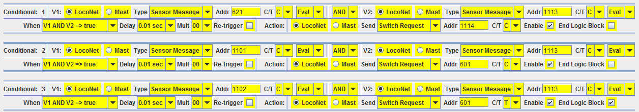
The inputs for this logic block are 621 (the track circuit for turnout 601), Rotary switch inputs 1101 and 1102, and the push button 1113. Conditional 1 looks at 621. If it is closed (C), it doesn't throw the turnout. That means that there is a train on the turnout. It does, however, turn off the red blinking LED (1114 to C). This lets you know that something is amiss.
Provided that the turnout is not occupied, Conditional 2 is true if the rotary switch is in position 1 (1101 = C) and the push button in pressed (1113 = C). It then closes the switch motor for 601, which lines it for track 1. Conditional 3 is true if the rotary switch is in position 2 (1102 = C) and the push button is pressed (1113 = C) then 601 changes to T (thrown), which lines it for track 2. That ends the logic block, so if nothing else has happened, nothing happens to the switch machine for turnout 601.
This continues on for the other switch machines. the last turnouts in each sequence, 603,605, 608, and 611, work just like 601 does, just with different inputs and outputs. Other turnouts have more inputs that can effect them, so there are more conditionals in those logic blocks.
The first turnout in the yard ladder, 606, needs to be thrown or closed for every track selected. Since this is true, there is no "do nothing" option. If tracks 1 - 6 are selected, turnout 606 is closed (C). In all other cases, 606 is thrown (T). We can use the way that the logic blocks are evaluated to our advantage here. Here are the last three statements in the logic block for 606:

Note that Conditionals 18 and 19 look very similar to what we had for turnout 601. Before these were inputs for 1101, 1102, 1103, and 1104, and of course 626, the track circuit, at the beginning. On Conditional 20, if the rotary switch was not on any of these positions, if must be on position 1107, 1108, 1109, 1110, or 1112, and we don't really care which. In any of these cases, 606 needs to thrown (T). By the time it gets to Conditional 20, we know that track 1 - 6 were not selected, so throw that switch!
Remember the logic for the green LED on the panel? That already works to make it turn on if the turnouts are lined to the same track that the rotary switch is set to, so when the switch machines are thrown properly, the green LED turns on and the red blinking LED turns off. Now we're done and you can go back to the first post in this series and look at the video there and know how it works.
Good to see that things are coming along nicely.
ReplyDeleteBy the way, you should check out these:
http://www.lux-modellbau.de/ Choose "Produkte" and then "N". They have a wagon with a vacuum cleaner and one that polishes the track to get rid of oil etc. I bought the H0 version, and it is the best investment ever. No more trains stopping because the track is dirty etc. They are a tad expensive, but well worth it.